
Miscellaneous
In PLC Options, select Function Parameters to access Miscellaneous.
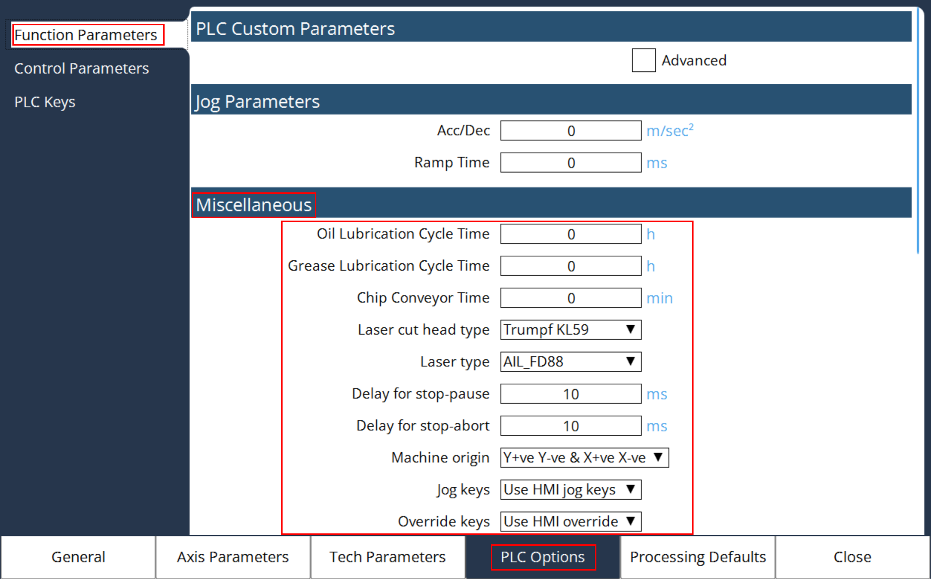
Oil Lubrication Cycle Time
This defines the interval of Oil lubrication cycle to be carried out in the machine before start of the program.
If this value is > 0, then the Oil cycle function will be activated in the PLC.
Grease Lubrication Cycle Time
This defines the interval of Grease lubrication cycle to be carried out in the machine before start of the program.
If this value is > 0, then the Grease cycle function will be activated in the PLC.
| If both Oil & Grease cycle time are > 0, then the Cycle program will be activated based on the maximum time of Oil & Grease lub cycle. |
Chip Conveyor Time
This defines the maximum time of Chip conveyor motion.
If activated via external key, the Chip Conveyor will run for this defined time & stop.
If activated by the start of program, then after the completion of program, it will run for this time & stop.
If this value is > 0, then the Chip Conveyor function will be activated in the PLC.
Laser cut head type
Following are the list of Cutting Head Type supported in the PLC:
00 : No Head
01 : Precitec
02 : Procutter EG8030
03: Procutter2.0 EG8050
Select the appropriate head used in the machine and accordingly the PLC function will be activated.
Laser type
Following are the list of Laser Type supported in the PLC:
00 : No Laser Source
01 : IPG_YLS Laser
02 : GSI Laser
03 : Rofin Laser
04 : IPG_YLM Laser
05 : IPG_YLR Laser
06 : nLight Laser
07 : Raycus Laser
08 : Trumpf Laser
09 : SPI Laser
Select the appropriate laser used in the machine and accordingly the PLC function will be activated.
Delay for stop-pause
This defines the delay time of Stop button (1st press) to pause the program. If the input exists more than this delay time, then the program is paused.
Delay for stop-abort
This defines the delay time of Stop button (2nd press) to abort the program. If the input exists more than this delay time, then the program is aborted.
Machine origin
This defines the origin point of the Machine with axis direction definition as follows:
0 : X-, X+ & Y+, Y-
1 : X-, X+ & Y-, Y+
2 : X+, X- & Y-, Y+
4 : X+, X- & Y+, Y-
8 : Y+, Y- & X+, X-
16 : Y+, Y- & X-, X+
32 : Y-, Y+ & X-, X+
64 : Y-, Y+ & X+, X-
Jog keys
Following are the options of Jog Keys assignment:
0 : HMI keys - will use the HMI keys to jog the axis
1 : External Axis Sel & Jog keys - Axis selection & jog keys are used in Machine
control panel
2 : External XY Jog keys - X+ X- / Y+ Y- key assignment
According to the above selection, the Jog key function is activated in the PLC.
Override keys
Following are the options of Override Keys assignment:
0 : HMI - will use the HMI Override keys
1 : Rotary Switch (Gray Code) - Override values depends on the position of
rotary switch
2 : Potentiometer - Override values depends on the potentiometer analogue input
3 : Encoder - Override values depends on the encoder position
4 : Buttons - Override - & Override +; buttons to change the override values
According to the above selection, the Override key function is activated in the PLC.