
Axis Properties
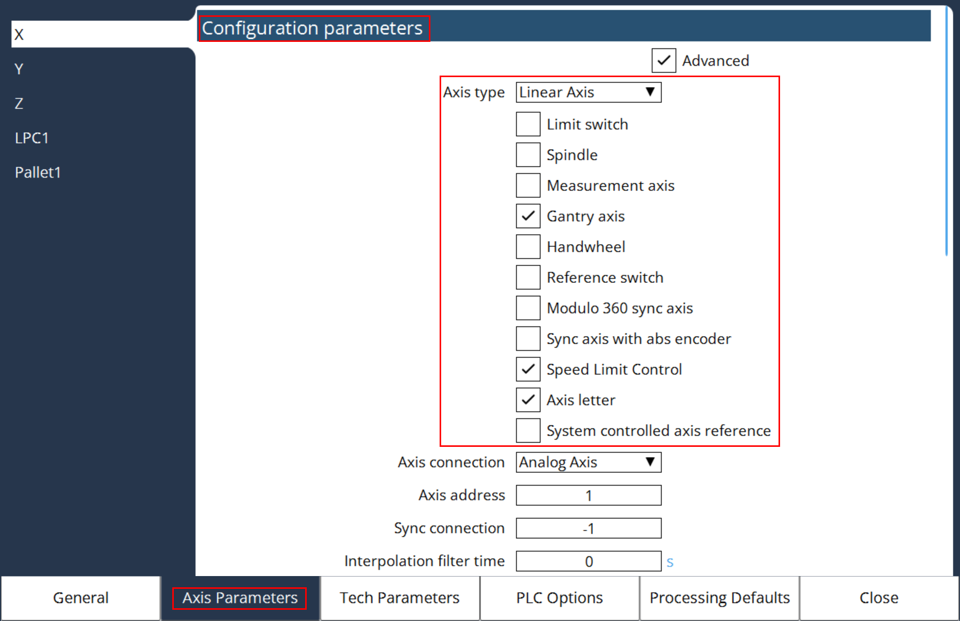
Axis properties specifies various axis characteristics.
| Bit | Value in the MC | Meaning | ||||||||||
|---|---|---|---|---|---|---|---|---|---|---|---|---|
0 |
0 |
Linear axis |
||||||||||
1 |
0 |
Observe end switch |
||||||||||
2-3 |
0 |
Normal axis |
||||||||||
4-5 |
|
|||||||||||
6 |
0 |
Normal axis |
||||||||||
7 |
0 |
Normal axis |
||||||||||
8 |
256 |
Reference switch is normally open, only for axes with analog interface. The reference switch is set by default to normally closed. |
||||||||||
9 |
512 |
Modulo 360° synchronous axis, only possible for rotative synchronous axis with power of two pulses for 360°, e.g. 4096. |
||||||||||
10 |
0 |
Synchronous axis/axis without absolute encoder, i.e. reference point traverse is necessary |
||||||||||
11 |
0 |
Velocity limit monitoring enabled |
||||||||||
12 |
0 |
Axis is a NC axis if it has an axis letter |
||||||||||
13 |
8192 |
For axes with a field bus interface, a system controlled reference point traverse is performed before a servo controlled reference point traverse is performed Consider the following aspects: MK Axis Homing Mode must be set to 1. Other types of reference point traverses are not supported. Determine acceleration and speed of the reference point traverse in the following machine constants: MK Axis Homing Velocity1, MK Axis Homing Velocity2, MK Axis Homing Acceleration1 and MK Axis Homing Acceleration2 Set MK Axis Exact Stop Lag Window and MK Axis Exact Stop Time Window to reasonable values, otherwise the reference point travel becomes inaccurate or the axis may buck at the end of the system controlled reference point traverse. For Gantry axes, the initial alignment of all involved axes are only performed with means of the reference switches of the master and slave axes. Small corrections can be applied with the synchronous offset which will be performed at the end of the procedure. Therefore MK Axis Synchronous Offset has to be handles with care. Set it to 0 or small values that can be tolerated by the mechanics. The reference switch has to be connected to the appropriate input of the servo controller. Configure the input in a way, that the active state is displayed as a logical '1' in the input object, irrespective of whether the switch is normally open or closed (for DS402 normally Bit 2 "home switch" in the object 60FDh). Bit 8 in MK Axis Properties / MK Achsenart is not supported to invert reference switch signals for field bus axes. Set the homing mode (for DS402 usually the object 6098h) to "Homing on the current position" (Homing method 35 in the DS402), if no servo controlled reference point traverse should be performed after the system controlled reference point traverse has been performed. |
In order to set the desired bit, the value from the table must be added to the value of the MC.
Example: For a rotation axis, which should ignore the end switch signals and for which Modulo 360° is programmed (where the sign determines the movement direction), the value 19 (= 1 + 2 + 16) must be entered (bit 0, 1 and 4).
The spindle number can be alternately defined via MK Spindle Index Assignment .
A gantry axis represents a special form of a synchronous axis. Here, there is a mechanical coupling between master and slave axes. In contrast to the simple synchronous axes, the reference point traverse will be synchronously executed for gantry axes with analog interfaces.