
Axis Connection
MK DRV CAN Axis

CAN Axis allocates the node numbers to the CAN bus application axis numbers and, together with MK DRV Analog Axis, MK DRV EtherCAT Axis and MK DRV Virtual Axis defines which application axes are configured.
For each non-assigned node number, the value-1 must be entered. The allocation of the axis letters to the given application axis numbers is achieved via MK CFG Axis Letter Assignment.
The MK provides one parameter (application axis) for each node number at the bus. The allocation of the node numbers to the parameters is fixed sequentially from 1 through N. The maximum number of entries depends on the used controller:
| Parameter | Interface | Node-ID | Controller |
|---|---|---|---|
1 to 12 |
CAN2 |
1 to 12 |
All |
13 to 16 |
CAN2 |
13 to 16 |
Only ENC66 |
17 to 32 |
CAN3 |
17 to 32 |
Only ENC66 |
33 to 48 |
CAN4 |
33 to 48 |
Only ENC66 |
If an index is entered at two positions within MK DRV CAN Axis, a forced coupling is created between two axes (synchronous axes).
MK DRV EtherCAT Axis

EtherCAT Axis allocates logical axis addresses at the EtherCAT bus to the application axis numbers and, together with MK DRV Analog Axis, MK DRV CAN Axis and MK DRV Virtual Axis defines which application axes are configured. For each non-assigned node number, the value -1 must be entered.
Instead of the logical axis address the application axis number is located in the MK DRV EtherCAT Axis. The number of effective entries is determined by the activation code from the number of possible axes, but a maximum of 64.
Starting with firmware version V2.92beta1, a device address (alias or explicit device address) for a logical axis number can be entered on the EtherCAT bus via the machine constant MK DRV EtherCAT Addresses/MK EtherCAT Addresses. In older versions, the addressing behaves like the value 0 in this machine constant (topological addressing).
Servo controllers with multiple axes get correspondingly more logical addresses. The internal EtherCAT addresses stay the same.
MK DRV Virtual Axis

Virtual Axis defines the virtual application axis number without physical
reference. The number of parameters depends on the controller:
EXC66: Maximal 16 parameters for up to 16 virtual axes.
EXC88/EXC880: Maximal 64 parameters for up to 64 virtual axes.
MK DRV Analog Axis

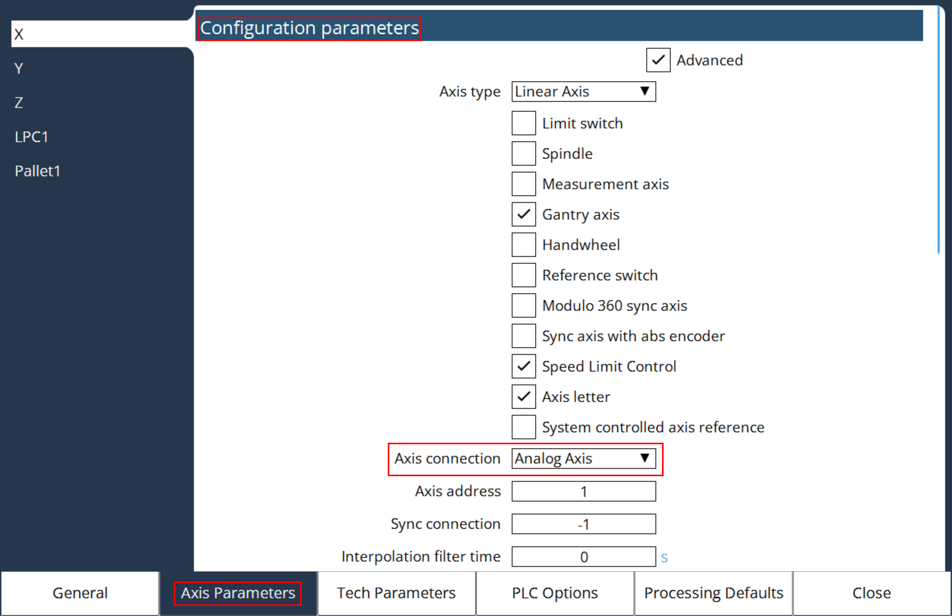
Analog Axis allocates the physical axis channels to the analog axis interface application number and, together with MK DRV CAN Axis, MK DRV EtherCAT Axis and MK DRV Virtual Axis defines which application axes are configured.
For each non-assigned axis channel, the value -1 must be entered. The allocation of the axis letters to the given application axis numbers is achieved via MK CFG Axis Letter Assignment.
This MC has as many parameters as physical axes that can be connected to the controller. The sequence is fixed and is referenced to the physical sequence of the axis outputs. this means:
-
Parameter: Channel 1 on axis interface card 1
-
Parameter: Channel 2 on axis interface card 1
-
Parameter: Channel 1 on axis interface card 2, etc.
If an index is entered at two positions within MK DRV Analog Axis , a forced coupling is created between two axes (synchronous axes).
Example:
Machine with X, Y and C axes; C with synchronous axis (C')
- MK DRV Analog Axis 0, 1, 2, 2, -1, -1,….;
- MK CFG Axis Letter Assignment 0, 1, -1, 2, -1, -1, -1,…;
On the first axis interface, axis X is connected to channel 1 and Y, to channel 2. On the second axis interface, axis C is connected to channel 1 and C', to channel 2. A forced coupling was defined for the third and fourth physical axis channel, under the axis letter C. The axis on the third axis channel is the leading axis (master).